This page explains some of the issues associated with the design and construction of the high pressure gas injection system used in my magnetoplasmadynamic thruster design. Since this design does involve gas flow issues, it is suggested that you also read up on compressible flow first if you're not already familiar with it. The first design parameter that needs to be decided is the desired flow rate of the system. In my case, the flow rate of the injection system was the limiting factor in other areas, so flow rates as high as possible within budget constraints were sought. This also suggests a high delivery pressure, so this portion of the design is limited only by the components and materials that can reasonably be obtained that can withstand these pressures. The design started with the choice to make the working gas Argon. Among its various properties that made it attractive as a propellant, the final decision came down to availability and cost. Argon is used in welding applications such as the electric arc welding of aluminum and when mixed with carbon dioxide for electric arc welding of steel, so it was readily available at a reasonable price at welding supply shops in compressed gas cylinders. Cylinder pressures for Argon are typically around 2,000-3,000 PSI, which requires a pressure regulator in order to supply it at lower pressures. I found a good Harris 3500-125 high flow Argon regulator on eBay for approximately $40 (what a steal!) The maximum delivery pressure on this unit is about 125 PSIG (i.e. PSI as read from a gauge. This reading is the pressure above ambient, so a reading of 0 PSIG means at ambient pressure. Ambient pressure is about 14 PSI, which could be expressed as 14 PSIA, or 14 PSI absolute.) Let's take a quick look at the flow data from the Harris datasheet for this regulator. [1] 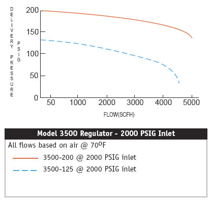 Fig. 1: Argon Regulator Flow Data This datasheet assumes that the tank can deliver at least 2000 PSIG to the regulator. If we read across from 125 PSIG delivery pressure, we find that this regulator can deliver Argon at a rate of about 1000 SCFH (standard cubic feet per hour. A standard cubic foot is the volume of the gas at standard temperature and pressure. Standard temperature and pressure are 20 degrees Celsius and 1 atmosphere, respectively.) This is equal to a little more than 0.25 standard cubic feet per second, and isn't very much. We can get around the regulator's limited flow rate by using a surge tank, which is simply a large pressure vessel connected downstream of the regulator. This works by allowing the regulator to (relatively) slowly fill the surge tank until it reaches a high pressure, which will support much higher flow rates for the brief period of time that it is needed. The folks at Aimtek in Auburn, Massachusetts were kind enough to sell me a used E size oxygen tank which worked very nicely as a surge tank. 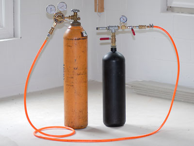 Fig. 2: Argon Cylinder, Regulator, and Surge Tank Assembly The next major component selection was the gas solenoid that would control the gas flow from the surge tank and regulator. In light of the 125 PSI maximum working pressure from the regulator, this was relatively easy. Not surprisingly, I found a something on eBay - an AAA SS40 gas solenoid with a 160 PSI maximum working pressure for about $50. The solenoid is shown below connected to the surge tank. 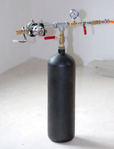 Fig. 3: Gas Solenoid Connected to Surge Tank For the purposes of analyzing the gas injection system, we can consider the solenoid as emptying directly into ambient air pressure since the gas solenoid presents a critical orifice to the gas flow. This greatly simplifies the job of calculating the gas flow rate, since this data is directly available from the SS40's datasheet. [2] 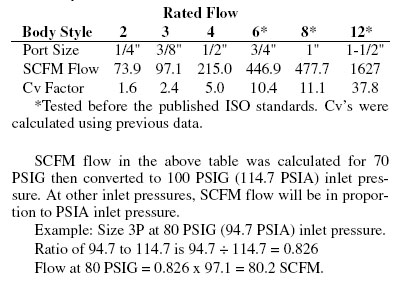 Fig. 3: SS40 Gas Solenoid Datasheet Excerpt Using this data, I calculated the gas flow rate from the solenoid to be approximately 327 SCFM or 5.45 SCFS. This is much better than the 0.25 SCFS obtained directly from the gas regulator 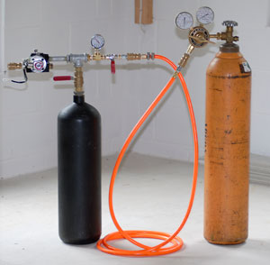 Fig. 4: Complete Assembly
Working with compressed inert gases such as Argon is generally safe, however, leaks or accidental discharges can quickly displace oxygen leading to death by suffocation. Always work in a well ventilated area, check for and fix leaks, and handle gas cylinders with care. Dropping a gas cylinder can shear off the valve, releasing large amounts of gas and propelling the cylinder to dangerous velocities.
I hope to raise the working pressure of this system significantly, and thereby increase the gas flow rate. The largest obstacle at this point is finding a gas solenoid that can work at considerably higher pressures, with large diameter connections, for a reasonable price. Unfortunately, these sort of things don't show up on eBay very often. I'll also need to find a high pressure inert gas regulator, which is a significantly easier though much more expensive task. The hosing will also need to be replaced, but this is something that I can deal with when I get there. References [1] Tech Data, Regulator Technical Data 3500, Harris Calorific, Inc., Mason Oh. [2] Valve Catalog #28, Complete Air Valve Catalog, AAA Products International, Dallas Texas. [ Back to MPD Thruster ] [ Back to Main ] visitors since September 2007 Questions? Comments? Suggestions? E-Mail me at MyElectricEngine@gmail.com Copyright 2007-2010 by Matthew Krolak - All Rights Reserved. Don't copy my stuff without asking first. |