As I've mentioned previously, the main purpose of a capacitor bank for the purposes of high power experiments is to deliver as much power as possible as quickly as possible, and in order to do that the capacitors have to be able to deliver very large currents. In order for this to be possible the parasitic resistances and inductances of the connections between capacitors need to be minimized. This means wide flat conductors with large cross-sections. For any budget-minded design the first step is probably going to be locating a source of capacitors. In my mind, two categories of capacitors stand out - electrolytic capacitors and pulse capacitors. Pulse capacitors are typically large and have maximum voltage ratings in the thousands of volts and are generally expensive. Electrolytics, on the other hand, are limited to about 500V, are smaller, and are reasonably cheap if you can get them as surplus. I went with electrolytic capacitors, as I found a source for 128 Philips 3,600uF 350VDC 400VDC Surge rated capacitors that were recovered from old GE medical imaging equipment on eBay for about $25 per 8 capacitors ($400 total). 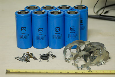 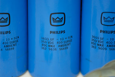 Fig. 1: Capacitors Luckily, these came with all of the necessary hardware, including bleeder resistors and mounting braces. I used all of the original bleeder resistors, which worked out to one 20kOhm resister per capacitor. The bleeder resistors are also important, as the capacitors could otherwise retain a dangerous level of charge for long periods of time. With the bleeders, any remaining charge will be slowly removed so that you don't get a nasty or deadly shock if you forget to completely discharge them. It's important to also know the time constant of the resistor / capacitor combination. This tells you how quickly the capacitors will discharge through the bleeder resistor. The time constant can be calculated as  Eq. 1: Time Constant The time constant is equal to the time it takes for the capacitor to discharge to 37% of its original voltage, in this case about 72 seconds. As a rule of thumb, a capacitor is generally considered discharged after 10 time constants, or in this case, about 720 seconds (12 minutes.) Using a smaller value resistor will decrease the time it takes the capacitor to discharge, but will increase the amount of power that will be dissipated by the resistor. The power dissipated by the resistor is given as  Eq. 2: Power Dissipated in Resistor In this case, each bleeder resistor will consume about 6 Watts of power if the capacitors are charged to 350V. Selecting a bleeder resistor is then a compromise between the time for the capacitors to discharge (safer) and the amount of power dissipated in the bleeder resistors (more efficient.) The next major decision that needs to be made concerns the conductors that connect all of the capacitors together and something called skin effect. Skin effect occurs whenever current through a conductor changes abruptly, and limits higher frequency currents from penetrating further into the conductor. So, if you have a large current and have selected a conductor that would be appropriate for DC currents, you'll find that at high AC frequencies the current will only travel through the portion of the conductor close to the surface. This means that perhaps a significant portion of your conductor is being wasted, and that the conductor may heat much more than expected since the current is going through an effectively smaller conductor. The skin depth is given as [1] 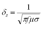 Eq. 3: Skin Depth for good conductors where f is the frequency, mu is the magnetic permeability of free space, and sigma is the conductivity of the conductor. To simplify this problem, let's assume that the discharge of the capacitors' energy completes in 2.5ms, and that the current waveform approximates half a sine wave, and that the conductor is aluminum. This corresponds to a frequency of 200Hz, with aluminum having a conductivity of 3.78x10^7[2]. Plugging these values into equation 3 yields a skin depth of roughly 5.8mm. Since the skin effect applies to the top and bottom surface of a conductor, the maximum thickness of a plate of aluminum through which this discharge will use then entire volume of the conductor is 1.16cm (a little under a half an inch.) So there you have it, the aluminum buss bars used to connect the capacitors in the capacitor bank should not be more than about 1/2" thick, though they can be as wide as we like to accommodate large currents. The bleeder resistance and the conductor thickness are the two controlling factors that decide how to best construct the capacitor bank. With both of these parameters defined, we can get to work. I first assembled each set of four capacitors into a string using 1"x1/8" aluminum bars (from Home Depot) with bleeder resistors connected across the buss bars. Four of these strings of four capacitors were then mounted to a Lexan plate, and connected in parallel with 1.5"x1/8" aluminum bars. A total of 8 such plates were constructed, and mounted into two towers of 64 capacitors, with the plates being connected with two runs of 1.5"x1/8" aluminum bars. The construction details are shown below. 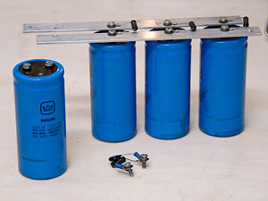 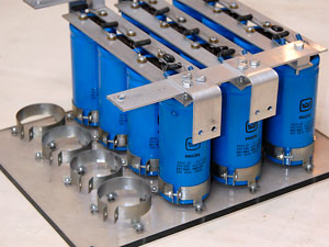 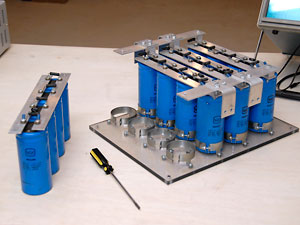 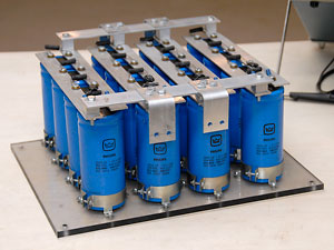 Fig. 2a: Capacitor Bank Construction 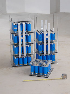 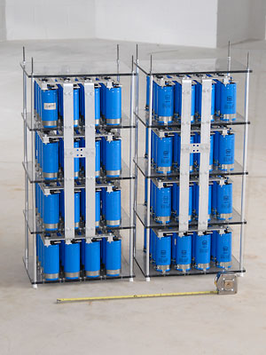 Fig. 2b: Capacitor Bank Construction When both stacks are connected in parallel they have a total capacitance of 0.46 Farads at 350V, with 128 20kOhm bleeder resistors connected in parallel (equivalent to 156 Ohms.) This works out to 28,200 Joules of energy stored at 350V, and 784 Watts dissipated in the bleeder resistors at 350V.
Capacitors can store lethal voltages for long periods of time, or even accumulate lethal voltages over time. All capacitors should have a bleeder resistor connected at all times to prevent charge from building up and to safely discharge the capacitor when not in use. Even with these precautions, always treat capacitors as if they are charged, and properly discharge them before working with them. You are ultimately responsible for your own safety - so make sure you know what you're doing before you do it!
Lowering the inductance of the connections within the capacitor bank is an important factor in capacitor bank performance for discharge type experiments. The wide flat conductors shown earlier help to reduce this inductance, but there are other configurations that allow for lower total inductance. In the previous design conductors are laid horizontal in and edge-to-edge configuration. The inductance can be lowered if the conductors are slightly wider, and if they're set back-to-back, as shown below. 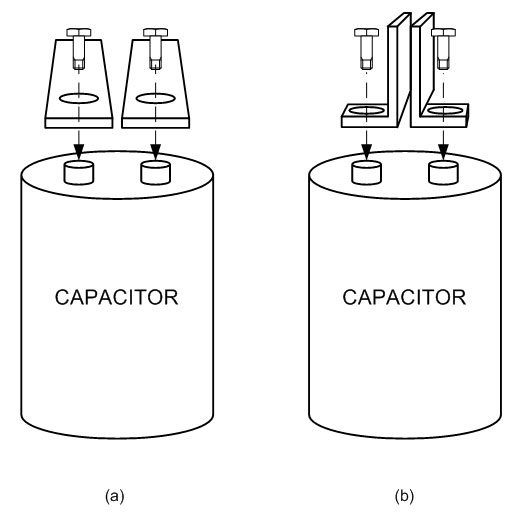 Fig. 3: (a) Normal Construction (b) Low Inductance Construction The low inductance construction method shown in figure 3b is only necessary for extremely low inductances in conjunction with low ESL capacitors. Otherwise, the construction shown in figure 3a is sufficient. References [1] Fawwaz T. Ulaby, Fundamentals of Applied Electromagnetics, Upper Saddle River: Pearson Prentice Hall, 2004, pp. 277 [ Back to MPD Thruster ] [ Back to Main ] Questions?
Comments? Suggestions? E-Mail me at MyElectricEngine@gmail.com
Copyright 2007-2010 by Matthew Krolak - All Rights Reserved. Don't copy my stuff without asking first. |